Call us : +1-281-261-4628


A few examples of Fitness for Service evaluations performed by Pressure Equipment Engineering Services, Inc. are as follows:
- Fitness for service evaluation was performed for the top bed of a stainless steel reactor with the intent to calculate the maximum permissible pressure differential allowed by the structural capacity of the bed. The packed bed had 3 distinct stainless steel fabricated beams. The bed was getting plugged during operation. This was causing significantly higher pressure drop on the bed leading to very high stresses in the beams. The intent was to shut down the reactor before the pressure drop reaches a scenario causing the structural failure of the bed. The structural calculations (per AISC code) were performed to check the stresses in the beams, welds and the beam support grating. These structural calculations were automated using MathCAD to calculate the maximum allowable pressure drop through the bed for design case, upset case and failure case. For each of these cases, the limiting pressure drop for the three distinct structural beams and the associated grating support was calculated. The design pressure drop through the reactor bed was 100 psig. The maximum allowable pressure drop for the upset case was specified to be 138 psig. At this pressure drop, all the design criteria were satisfied and this pressure drop was safely permissible. The maximum allowable pressure drop for the failure case was specified to be 158 psig. At this pressure drop, the code allowable stress criteria were not satisfied and the structural components start to yield. Using the pressure drop guidelines specified by these set of calculations, the plant increased the safe operating time before the next shut down.
- Fitness for service evaluations were performed for hundreds of vessels and heat exchangers experiencing generalized corrosion. Based on the half life criteria of the inspection codes, more frequent inspections must be performed for these vessels and heat exchangers to avoid violating the code or jeopardizing the safety of the equipment. In some cases, these vessels and exchangers start approaching scenarios indicating life depletion because of the loss of intended corrosion allowance. The code calculations are performed (using Pressure Vessel & Heat exchanger COMPRESS) for each component of the vessel / exchanger to calculate the minimum retirement thickness for that component for the intended design parameters. The combined set of minimum thickness for all components acts as a guide for future inspection interval for the vessel / exchanger. The calculated minimum thickness values are compared to the actual field measured values to make sure that there is sufficient future safe and useful life available for all the components of the vessel / exchanger. If enough life is not available for several components, then de-rating of vessel / exchanger may be necessary. In case one or two components are limiting the MAWP, local repairs may be specified to maintain the original MAWP of the vessel / exchanger.
- Fitness for service evaluation was performed for several pressure vessels experiencing temperature lower than the MDMT. The fitness for service criteria was used to evaluate the MSOT (Minimum Safe Operating Temperature) for the vessel. Based on the evaluation, it was concluded for some cases that the MSOT for the vessel was below the intended temperature of operation and thus the vessel was re-rated to the lower requested temperature. However, when the MSOT for the vessel is above the intended temperature of operation, the vessel can not be re-rated to the lower requested temperature.
- Fitness for service evaluation for several tall vessels was performed before being subjected to in-situ PWHT at temperature of 1150 °F. Sometimes the vessel is heat treated for the circumferential zone containing the repair areas and at other times, the vessel is heat treated using gas firing such that the entire vessel is subjected to PWHT temperature. The actual vessel stresses due to dead weight and wind loading are calculated at the location of the circumferential PWHT zone and compared to the allowable stress values. For cases where the actual stresses are within the allowable stresses, the vessels can be post weld heat treated without any external support. For the other cases, it is found that the vessel stresses exceed the allowable stress values. In these cases, it is recommended that the vessels must be supported with the help of a crane before PWHT is performed for the circumferential vessel zone.
- Fitness for service evaluation has been performed for several storage tanks where the storage fluid has higher density as compared to the density of the storage fluid. Fitness for service evaluation has also been performed for storage tanks where the storage tank walls are corroded as compared to the original walls of the storage fluid. Both of these scenarios lead to the tank wall stress levels above the allowable stress levels listed in the appropriate code. To avoid these high stresses in the tank walls, the fill height can be adjusted. Thus the final result of the fitness for service evaluation is the specification of the maximum fill height that is allowed for the given tank and the given storage fluid.
- Fitness for service evaluation was performed for a fixed tubesheet heat exchanger with flanged and flued expansion joint. The shell side of the exchanger had significant corrosion. The original shell side design parameters were 100 psig @150 °F and the original tube side design parameters were 50 psig @ 225 °F. The request was to see if both sides of the exchanger would be suitable for 600 °F. As a result of the significant corrosion on the shell side of the exchanger, the heat exchanger did not meet the TEMA thickness requirements. However, when mechanical integrity evaluation was performed, the exchanger was found to be fit-for-service satisfying ASME Section VIII, Div.- 1 requirements. It was also found that when both shell and tube side design temperatures are 600 °F, the thermal stresses are well above the code allowable stresses. After several iterations, it was found that the acceptable thermal stress levels can be achieved when the tube side design temperature is lowered to 520 °F. Hence, the heat exchanger was declared fit for service with the final shell side rating of 100 psig @ 600 °F and the final tube side rating of 50 psig @ 520 °F.
- Fitness for service evaluation was performed for the top bed of a stainless steel reactor with the intent to calculate the maximum permissible pressure differential allowed by the structural capacity of the bed. The packed bed had 3 distinct stainless steel fabricated beams. The bed was getting plugged during operation. This was causing significantly higher pressure drop on the bed leading to very high stresses in the beams. The intent was to shut down the reactor before the pressure drop reaches a scenario causing the structural failure of the bed. The structural calculations (per AISC code) were performed to check the stresses in the beams, welds and the beam support grating. These structural calculations were automated using MathCAD to calculate the maximum allowable pressure drop through the bed for design case, upset case and failure case. For each of these cases, the limiting pressure drop for the three distinct structural beams and the associated grating support was calculated. The design pressure drop through the reactor bed was 100 psig. The maximum allowable pressure drop for the upset case was specified to be 138 psig. At this pressure drop, all the design criteria were satisfied and this pressure drop was safely permissible. The maximum allowable pressure drop for the failure case was specified to be 158 psig. At this pressure drop, the code allowable stress criteria were not satisfied and the structural components start to yield. Using the pressure drop guidelines specified by these set of calculations, the plant increased the safe operating time before the next shut down.
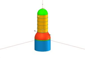
- (Confidential Project) Fitness for service evaluation was performed for a complex pressurized twin compartment machine separated by an oval transition piece. The first load case involved application of a bending moment for correcting the flange misalignment in one of the pressurized compartments. The second load case involved application of force and bending moment for correcting the thermal growth restrained by the frictional load for the second pressurized compartment. The third load case was a combination of the two load cases. The finite element analysis was performed using ANSYS software to complete the evaluation. The evaluation of stresses was based on ASME, B&PV, Sec. VIII, Div.-2, Appendix – 4 rules. Based on the fitness-for-service evaluation, it was concluded that all the stresses in the pressurized compartments and transition piece were within the code allowable stress limits for all the three load cases. Hence, the machine was found to be fit for service for the non-design load cases as specified above.
- Fitness for service evaluation was performed for a large diameter piping system containing new Pressure safety valve. To take care of the valve weight, new piping support location was added. The piping system was analyzed using the Pipe stress analysis software CAESAR-II. The sustained and expansion stresses in the piping were checked to make sure that all the pipe support locations specified were acceptable per the analysis. The end connections of the piping were checked by using the finite element software NOZZLEPRO. At the connection with the flare line, all the primary and secondary stress combinations were within ASME code allowable stress limits. At the connection with the 42” dia. pipe, the overstress condition was found for the given loads. It was recommended to use a 4” wide x 0.5” thick reinforcing pad. This eliminated the overstressing condition in the 42” dia. pipe. Thus, the existing pipe was fit for service with the new pipe support location and a new reinforcing pad at the intersection of 42” dia. pipe.
- Fitness for service evaluation was performed for a tall vessel which had severe corrosion for two courses of shell rings. The shell ring # 3 (from bottom) had corroded from original thickness of 0.375” to a thickness of 0.135” and shell ring # 2 (from bottom) had corroded from original thickness of 0.500” to current thickness of 0.270”. Hence, the available section modulus in shell ring # 3 was not sufficient to carry out the design wind loading for the vessel. This called for de-rating of the vessel as well as providing an external support system which would be capable of carrying the design wind load. The intent was that the vessel would be operated for a few months only and the corrosion rates would be controlled by modifying the process. The following three recommendations list the possible choices for reviving the vessel:
1.Replace shell ring # 3 and shell ring # 2 with new shell plates of 0.375” thickness and 0.500” thickness respectively.
2. Install a 9’-0” wide (Min.) X 3/8” thick plate (Material: SA-516-70) to cover shell ring # 3 (from bottom) with 3/8” fillet welds. This will cover the corroded shell ring # 3 and will extend a minimum of 6” beyond circumferential seam in either direction.
3. Install six (6) structural supports (60° apart from each other) around the vessel covering the shell ring # 3 and going approximately 2’ beyond the horizontal circumferential seams. The structural design was based on the availability of the I-beams (W6X15, Material: SA-36) in the scrap yard. The final size of each of these supports was calculated per structural engineering calculations in accordance with AISC. This design was meant to take care of the design wind loading only and not meant to provide any additional corrosion allowance or additional pressure rating for the vessel. Based on the thickness loss for the shell ring, the vessel must be de-rated from 125 psig @ 650 °F to 54 psig @ 650 °F.The first two alternatives were not implemented due to time constraint and delay in material procurement. The third alternative was the preferred choice because the plant could quickly make the vessel fit for service with the specified repairs. This was considered short term fix till the next turnaround.
- Fitness for service evaluation for a large spheroid vessel experiencing general corrosion. FEA using ANSYS was performed to complete the evaluation. The life of the vessel got extended by a few years. Some details of this analysis are enclosed herewith in the PDF format.
- Fitness for service evaluation for a horizontal reactor vessel for higher design loading. FEA using ANSYS was performed to complete the evaluation. The results of the analysis indicated that we did not need additional stiffener rings as was being pointed out by conventional stress analysis. Some details of this analysis are enclosed herewith in the PDF format.
- Fitness for service evaluation was performed for a storage tank when the hot liquid at 400 °F was to be suddenly introduced in the tank. The finite element analysis was performed using ANSYS software to complete the evaluation. The temperature distribution due to thermal gradient was calculated in the tank. Subsequently, this temperature distribution was used to calculate the thermal stresses in the tank. The evaluation of stresses was based on ASME, B&PV, Sec. VIII, Div.-2, Appendix – 4 rules. At the requested 400 °F, the thermal stresses were above the acceptable limits. Subsequent case runs concluded that it was safe to use maximum temperature limit of 350 °F for the hot liquid entry. Hence, based on the fitness-for-service evaluation, it was concluded that the temperature of the hot liquid for sudden introduction in the tank be limited to 350 °F.
- Fitness for service evaluation for the bottom head of a reactor experiencing pitting corrosion. FEA using ANSYS was performed to complete the evaluation. The life of the vessel got extended by a few years. Some details of this analysis are enclosed herewith in the PDF format.
Engineering Examples
Pressure Vessel Examples
A few examples of Pressure Vessel Design / Analysis performed by Pressure ...
Read More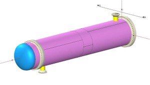
Heat Exchanger Examples
A few examples of Heat Exchangers Design / Analysis performed by Pressure ...
Read More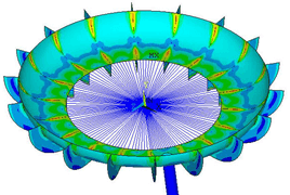
Fitness for service examples
A few examples of Fitness for Service evaluations performed by Pressure Equipment ...
Read More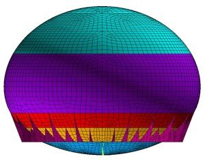
Finite Element Analysis Examples
A few examples of Finite Element Analysis performed by Pressure Equipment Engineering ...
Read More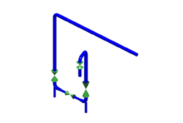
Piping Examples
A few examples of Piping Design / Analysis performed by Pressure Equipment ...
Read More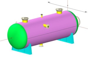
Minimum Retirement Thickness Calculations ...
The minimum retirement thickness values were calculated for 6'-6" dia. x 25'-0" ...
Read More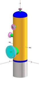
Pressure Equipment Certification Examples
The vessel V-109B had almost no information in the files. The vessel ...
Read More
Storage Tank Examples
A few examples of Storage Tanks Design / Analysis performed by Pressure ...
Read More
Structural Analysis Examples
A few examples of Structural analysis performed by Pressure Equipment Engineering Services, ...
Read MorePEESI Advantages

- Quick Response Time
- Quality Performance
- On-time job completion
- Increased Productivity
- Low Overheads for Clients
- Low Total manpower cost
- One-to-One Customer Support
- Client Satisfaction Guaranteed


